Commissioning a feedback loop is mostly unglamorous work. Tuning gets the attention, but a beautifully tuned PID will still misbehave if the pressure transmitter is scaled in bar while the faceplate reads psi, or if the valve opens when the controller tells it to close. Most loops that embarrass themselves on day one were never given a proper going-over while the plant was still in manual. What follows is the check-through that catches those failures before anyone is losing production over them.
Walk the Whole Signal Path
Start at the sensing element and finish at the final element, and treat every handover as suspect. In a typical loop that means the transmitter, the marshalling terminals, the input card, the PLC or DCS scaling block, the control block itself, the output card, the positioner and the valve. Each junction is somewhere a range, a unit or a sign convention can quietly change.
Read the loop drawing first, then read the actual configuration, and assume the two disagree until you have proved otherwise. Discrepancies between drawing and code are normal, and the drawing is usually the one that is wrong.
Scaling and Units: Prove It at Three Points
Inject a known signal at roughly 0 %, 50 % and 100 % of range and read the engineering value at the operator station, not just in the programming software. A single check at mid-range will hide a reversed span. Where you can, simulate at the card terminals as well as at the transmitter: that separates an instrument scaling error from a card or software scaling error, and saves an hour of arguing later.
The traps that keep catching people
- Range mismatch. A transmitter ranged 0–10 bar feeding a loop expecting 0–16 bar will look plausible at low values and go badly wrong at high ones.
- Double conversion. Units converted in the PLC and again in the SCADA tag. Worth checking whenever a number looks close but not quite right.
- Square-root extraction. Differential-pressure flow measurement needs it exactly once. Twice gives you a quietly non-linear loop.
- Live zero. A 4–20 mA signal carries its own fault detection: 0 mA means a broken wire or dead transmitter. Make sure that distinction survives into the fault logic.
- Sensor type. Thermocouple type, RTD wiring configuration and polarity are all easy to set wrongly and hard to spot from the trend.
Confirm Actuator Direction Before You Let Go of Manual
With the loop in manual, step the output up in small increments and watch the process variable. It should move the way the control philosophy says it should. If the PV falls when the output rises, you need to know that now, not when the controller is asked to correct a disturbance.
Then check the rest of the chain: valve action (air-to-open or air-to-close), positioner sense, and motor rotation on anything three-phase. Keep a hand near the stop. On a valve that has been overhauled, verify actual travel at both ends — plenty of valves will not seat below about 3 % output or will not fully open above 95 %. Limits set outside that real travel are decoration.
Finally, confirm controller action: direct or reverse. A reverse-acting process with a direct-acting controller gives you a runaway the instant the loop goes to automatic.
Fail-Safe Behaviour Is a Decision, Not a Default
Someone has to write down what the loop does for each failure, and it should be someone who understands the process, not whoever is closest to the configuration laptop. Work through the list deliberately:
- Loss of instrument air
- Loss of electrical power to the final element
- Loss of the measurement signal, or a frozen value
- Loss of communication between controller and I/O
- Controller or processor fault
For each one, decide the required final-element position and prove it by pulling the relevant supply or simulating the fault. Spring-return actuators do this for you, provided the spring is set for the direction you actually want. Avoid "hold last output" unless the process is genuinely safe sitting still; a frozen output on a loop that needs continuous correction is rarely the safe answer.
Also settle what the controller does when the PV is bad. It should stop integrating, raise an alarm and hand over to a defined state. A controller that keeps integrating against a stale value will wind up and then slam the valve when the signal returns.
Limits, Clamps and Anti-Windup
Set output clamps inside the actuator's usable travel, set rate limits where a fast stroke would upset something downstream, and configure integral windup protection. Then test it: hold the output saturated for a few minutes and confirm the integral term does not accumulate a debt it will repay the moment the loop comes back into range.
Check alarm and trip settings with their deadbands and delays, including how they reset. A trip that will not clear without a manual reset is fine if that is intended and painful if it is not. And confirm bumpless transfer in both directions: the setpoint should track the PV while in manual, so switching to auto does not produce a step change in output.
The Twelve-Point Checklist
- Instrument range matches loop range; both are documented.
- Scaling verified at three points with a calibrated source.
- Units agree across transmitter, controller and operator display.
- Filter time constant and scan time recorded.
- Sensor fault detection configured and tested, including the live-zero case.
- Actuator direction confirmed by a bump test in manual.
- Valve travel and seating checked end to end.
- Fail-safe position decided for each failure mode and demonstrated.
- Output clamps set inside real actuator travel.
- Anti-windup configured and proven under saturation.
- Alarms and trips tested, with deadband, delay and reset behaviour.
- Bumpless manual-to-auto transfer proven, with setpoint tracking.
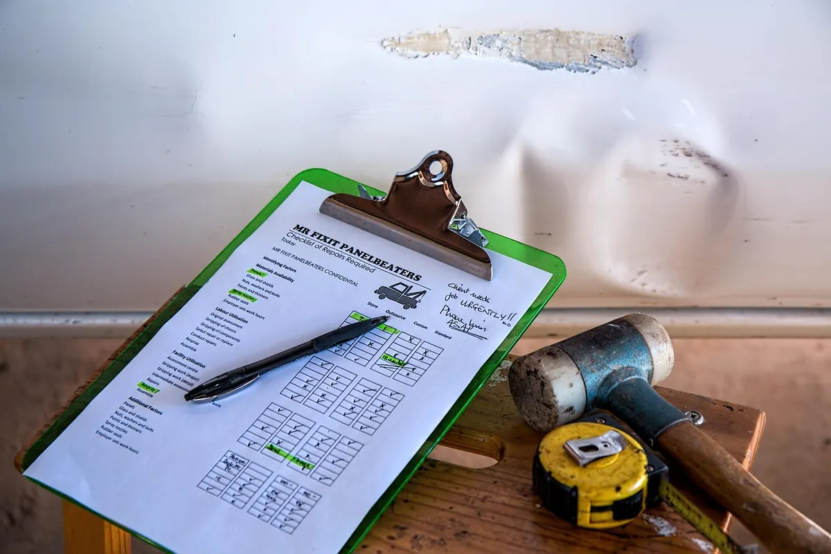
Print it. Write the as-left values on it and sign it. A checklist that lives in someone's head is a story, not a record.
The First Shift, and What to Leave Behind
Going to automatic is not the end of commissioning, it is the start of watching. Trend the PV and the controller output together for the first few hours and look at the shape of the response, not just whether it settles. Note the baseline: normal output, normal noise band, normal settling time. That baseline is what the next person will compare against when they are trying to work out whether something has changed.
Leave behind the tuning sheet, the as-left ranges, the fail-safe decisions and the loop drawing with corrections marked. It takes twenty minutes and it turns the next fault-finding session from archaeology into maintenance. Do it while the plant is quiet, because you will not get the chance once production is asking why the loop is in manual.
Photo: stevepb / Pixabay